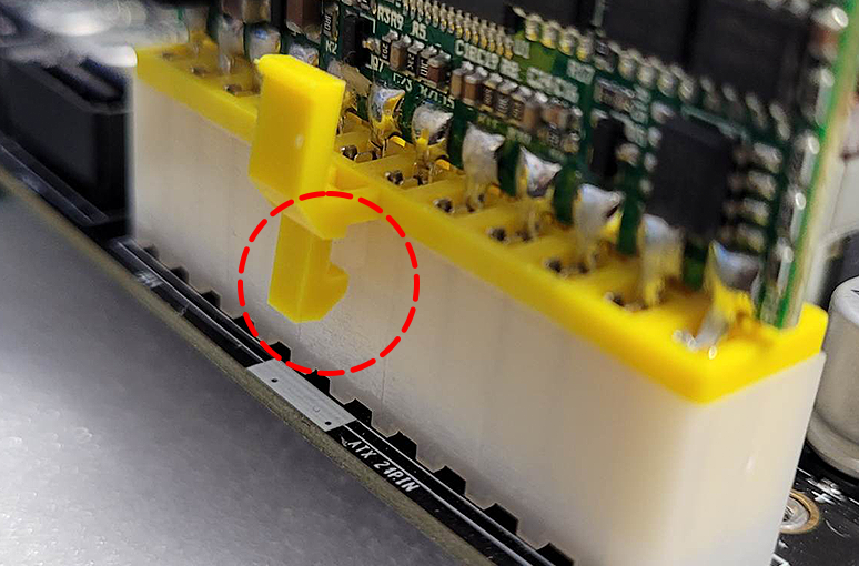
Hardware installation and Power ON

Get your Turing Pi V2 ready to turn on.

Prepare Compute Modules

Before inserting your Compute Modules, make sure to mount any cooler or heat sinks. Raspberry Pi Compute Modules, will need our CM4 Adapter board to allow it to be slotted into the 260-pin DDR4 slot.

Nvidia Jetson modules do not need any additional adaptors as they fit directly into the 260 pin DDR4 slot. We would recommend attaching any heatsinks prior to installation.

Raspberry Pi Compute Modues fit securely into the 100-pin, high density connectors on our CM4 adapter board, and generally will not require any additional fixing. If the unit is going to be used in edge computing or an application which may subject the unit to high levels of vibration, please ensure the modules are securely secured to the adaptor board. There is a 1.5 mm space between the RPI module and Adapter board.

rpi_cm_adapter_space.png

CM4_Adapterboard_back.pngCM4_Adapterboard_front.png


Note!

It's possible to mount the Raspberry Pi Compute Module at the wrong orientation. On the Adapter board there is an outline and the RPI module should fit into it correctly.

cm4_wrong_mount.pngcm4_correct_mount.png


SD Card (CM4 Adapter)

Before you insert Compute Modules, you can also install SD card, although the card is easily accessible from the side even when the modules are inserted. You can install OS on the SD card at this point, however we are going to use BMC to flash the SD cards later on.

cms_sd_card.png


Installing Modules

Inserting modules into the Turing Pi V2 DDR4 260Pin slot is quite straightforward. Simply align the sides and notch of the module with the slot, then press it vertically until you hear a click and the side arms fall into place.

slide_in_260pin.pngslide_in_260pin_done.png

How to remove the compute module

Removing the Compute Module is easy, you just need to release the white arms on both sides of the module at the same time. This will lift the module out of the socket, and you can easily remove it.

slide_out_260pin.png

Power

Turing Pi V2 and Compute Modules are powered from the ATX 24 Pin socket. Pico PSU or ATX PSU connector should fit only one way, please make sure it is slotted all the way in and the latch on the side is engaged. 

psu_latch.pngpsu_front.pngpsu_top.png

Network

Turing Pi V2 board features 2x RJ45 1Gbps network connectors, they are by default in bridge configuration. If you want to connect it to your already existing network, you only need to connect one port to your router/switch network device. If you have DHCP on your network, BMC and Compute Modules should get their IPs from it. To get the BMC IP, head over to the BMC specific page where we will go over all the options.

Powering ON

Once you apply power to the 24Pin socket, either by plugging in a power source for Pico PSU or switching the ATX PSU switch to ON, the BMC will boot up automatically. This will take a few seconds and you can observe the whole boot process with the serial console if you want (see the BMC dedicated section on how to do it). It should not take more than 10 to 20 seconds.

Once the BMC is booted up, you can either use the Front I/O pins or the physical buttons (Key1) to turn on the Modules 1 to 4 (Refer to the I/O section about pin outs). Simply press "Key1" for about a second, and you will see RED LEDs turning on next to the Module slots, meaning they are supplied with power. By default, this is a staggered power on sequence, meaning they turn on one after another.

power_led.png

On the other side of the Node1-4 slot, you can also find the network activity indicator LED.

nw_led.png


At this point, you should be ready to interact with the Compute Module or BMC. You can access BMC without any Compute Module inserted, check more on the BMC dedicated page.

RTC Clock Battery

Note: users reported that the RTC battery may restart or interfere with starting the BMC. We are investigating it at the moment. 

Insert Real Time Clock battery, CR 2032, into its holder. There is a notch on one side and a small metal lever on the other, slide the battery under the plastic notch and press down on the opposite side. It could be a tight fit, and you might need a small screwdriver to get the battery out later on.

rtc_bat.png


Was this article helpful?

15 out of 16 found this helpful
Have more questions? Submit a request

Comments (0 comments)

Please sign in to leave a comment.